Building a decoder
After finishing the bulk of the programming, I figured it would be better to build a nice little case with everything in it for long-term use (well, for as long as P2000 is in use).
What I used:
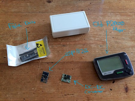
- 'Duino clone (ATMega328)
- ESP8266 (ESP-01)
- DC-DC Converter
- Old P2000 pager (an Infostream X-Stream X1)
- Plastic project case
- Some crap like LED's and USB connectors
I opened the pager and scrapped most of the power-consuming parts. It had a very bright red LED that obviously wasn't needed anymore. The beeper, vibrate-motor and display were removed as well. This reduced current consumption to a level where I was convinced I could pull of a little hack on the power supply (more about this later).
The pager is built around a 1.5v AAA battery as its power source. It uses an internal DC-DC converter to raise this supply to around 3 volts for various parts, but also uses the battery-power rail for various bits and pieces. The application processor and radio modules are on separate boards; as far as I know, this is a fairly common design choice as it makes it a lot easier to build pagers for different frequencies. Just swap the radio board and you've got a pager on a different frequency.
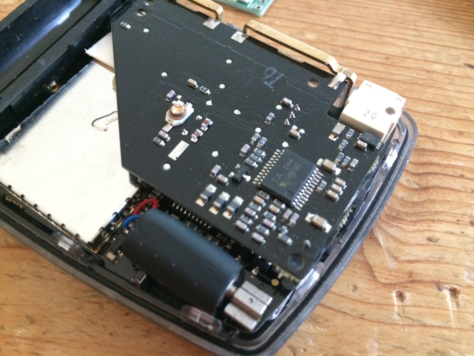
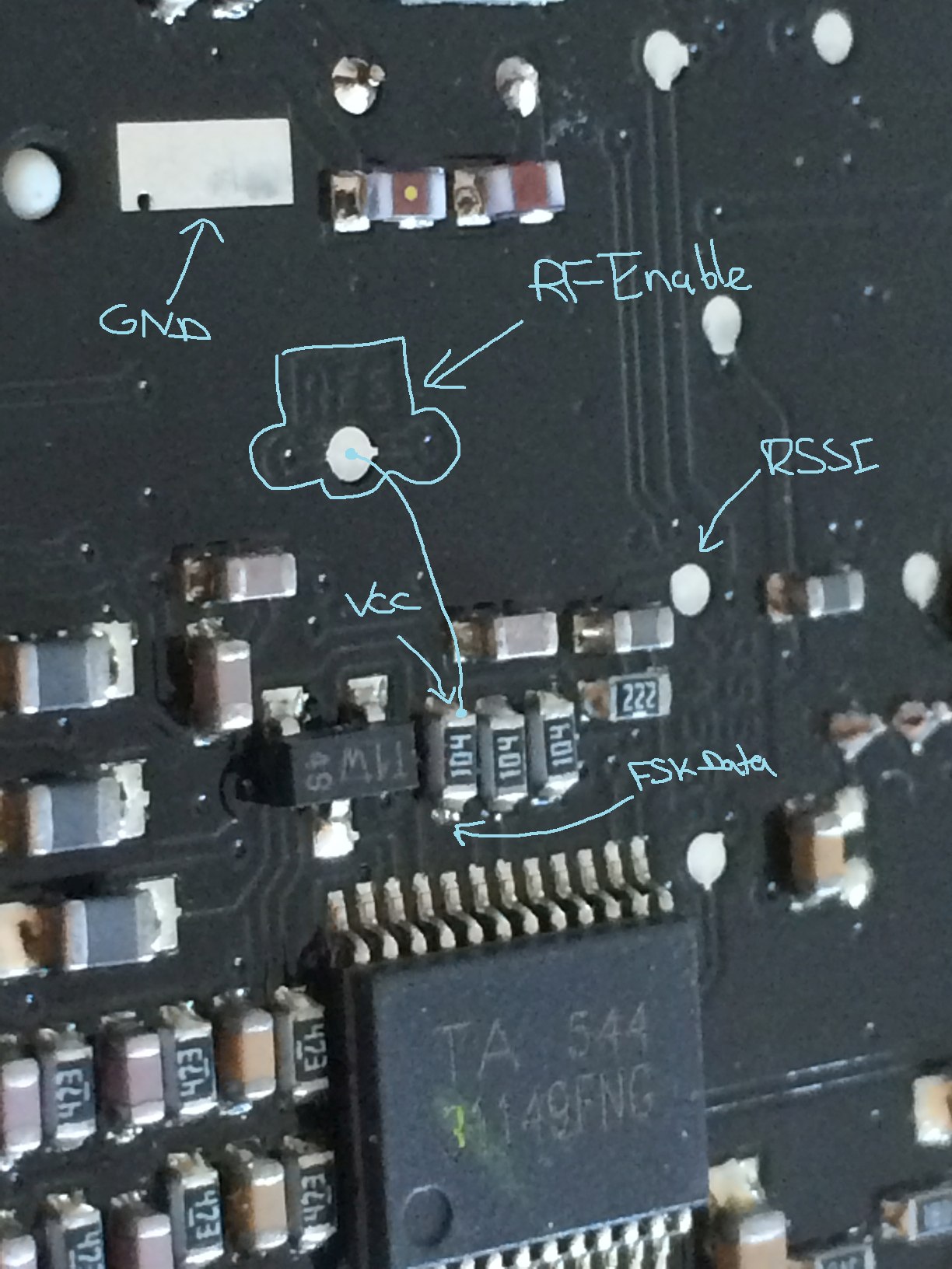
At first, I tried to use the radio board as a standalone board, but I failed to provide all the necessary signals to enable the receiver. The radio board uses a TA 31149 IC to demodulate the signals. The PDF for this IC is available online, and this helps us to determine what lines the FSK signals are on.
The board also has some convenient labels on the copper layer; RFE and RSSI were clearly marked. As a battery-saving measure, the radio board requires the application processor to provide a signal, enabling the receiver. As we want to receive all parts of all frames, we can't have the existing application processor switching off the receiver mid-frame. Fortunately, VCC used by the pull-up resistors is pretty closeby. Pulling the RFE pad high enables the receiver on a contiuous basis.
The pull-ups on the open-collector TA31149 outputs were a little high to my taste, so I added an extra parallel resistor to drop the resistance down a little bit. This improved the edges on the FSK line somewhat. Later, I realized that I could just enable the pullups on the ATMega328, but whatever.
Before: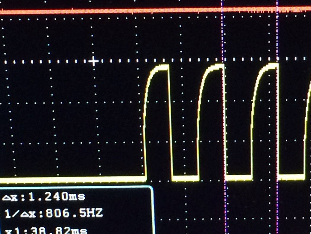 After:
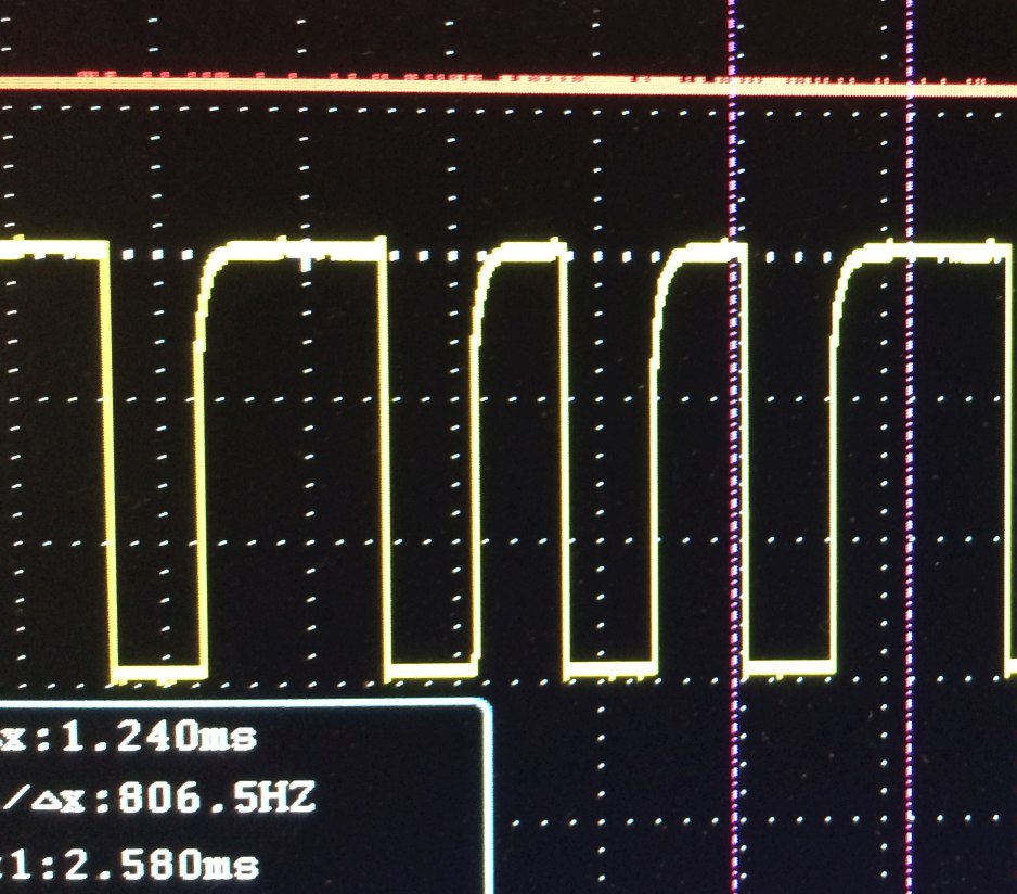
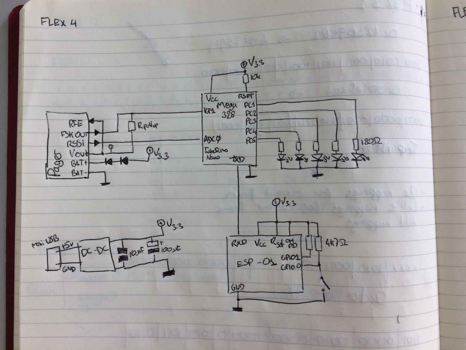
This is a little picture laying out the various connections on this pager; if you want to build something like this with the different pager, probe around until you have the FSK line and you're good to go.
 As much as I hate the arduino environment, its popularity really brought down the prices on these little boards. You can buy 'm from your favorite Chinese reseller, they're amazingly cheap and versatile. To enable them to work with my JTAGICE I had to get rid of this
 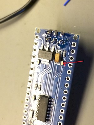 little capacitor over the RESET line. It breaks DebugWire, and my programming skills simply aren't good enough to write anything without extensive debugging.
The pager wanted 1.5v, but I only had space for one DC-DC converter in the little ABS case. As the power consumption for the pager was greatly reduced by getting rid of everything but the bare essentials, I was able to drop the 3.3v I needed for the ESP8266 and the ATMega328 down to about 1.9v by adding two diodes in series. I also wired a bunch of leds to the Arduino board. I had a lot of spare IO anyway, and you can never have too many pretty lights.
The DC converter was hooked up to a mini-USB connector and packed with kapton tape and aluminum foil, as I expected the proximity to the receiver board together with the switching pulses might degrade receiver sensitivity. As it turns out, It didn't matter an awful lot.
Wired it all up, added some glue and kapton tape, and stuck it all in the case. Total cost was about 20 euro's, including a second-hand pager bought online.
By the way, this is the schematic: