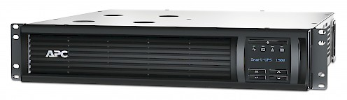
Adjusting the voltage on an APC SMT1500RMI2U to improve battery life
I bought my UPS second hand, but almost-new about two years ago. It's been working without a problem for some time, but lately it had been acting up. I've had a strange problem where every two weeks, th UPS would just shut itself down. I traced the problem down to the self-test, which was scheduled bi-weekly. Because of bad batteries, the self-test would fail outright, but because the short test was killing the UPS instantly, a 'poor battery condition'-warning never showed up in the device log. Measuring the battery terminals, the float voltage after charging on the dead battery was about 25,7v. This was set a bit too high; at 25,7v the 4 batteries died a bit too early to my taste. I don't exactly feel like replacing the batteries every two years, so I decided to see if it was possible to lower the float voltage. Turns out, this wasn't too difficult. A felllow hacker (vk2fro) on overclockers.com.au found that these UPSses use the same old serial interface that APC had been using for quite some time now, but it was being used by the LCD and control subsystem. There is still a header on the board, that can be used to talk to the UPS and adjust the voltage. The signal levels are TTL.
This guide is not a replacement for the excellent guide on overclockers.com.au, but serves as a guide to see how the same kind of modification can be done on the SMT1500RMI2U rackmount unit.
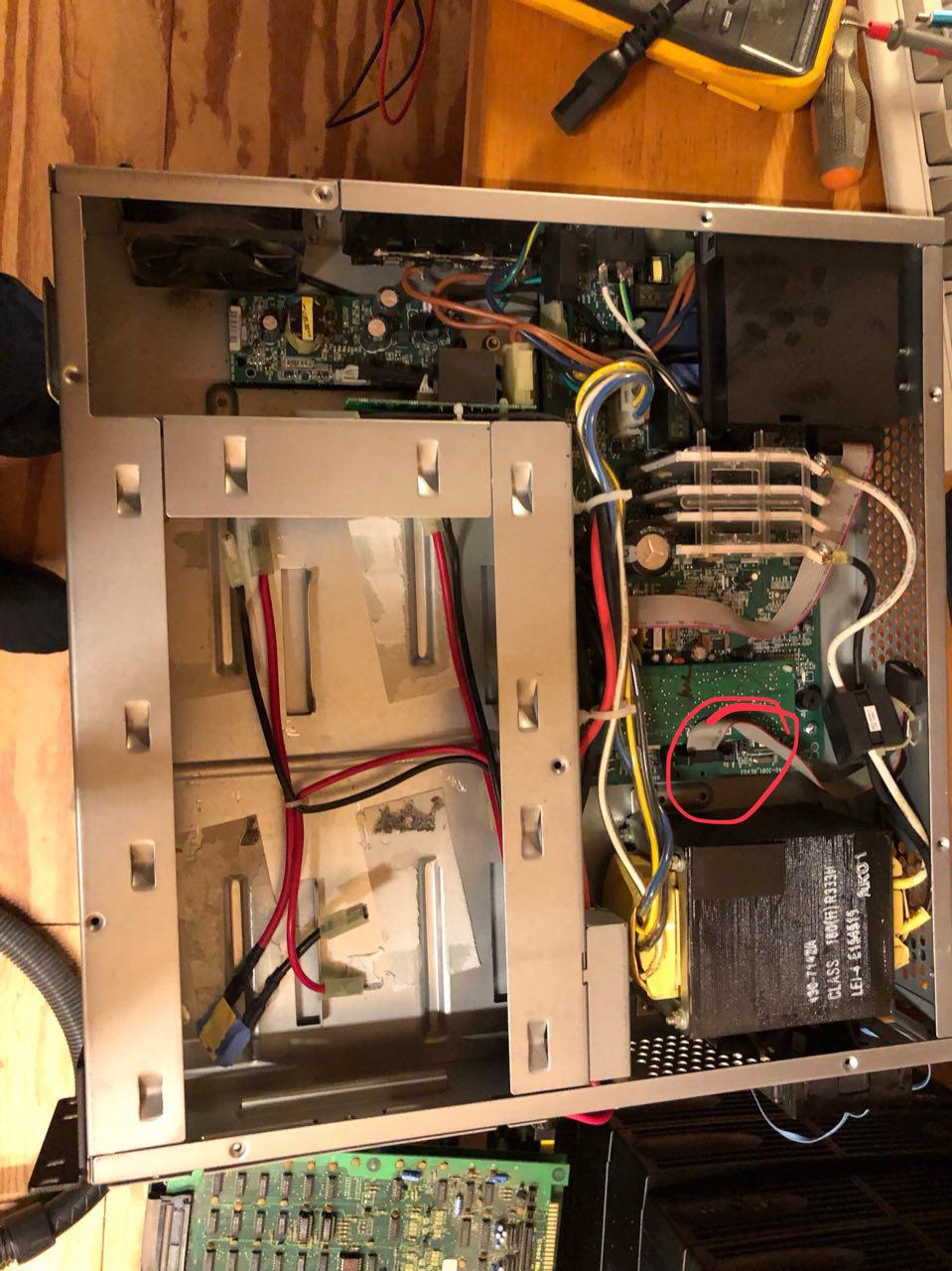
Start by taking off the top panel. It is held in place with about 9 screws. Removing the top panel will
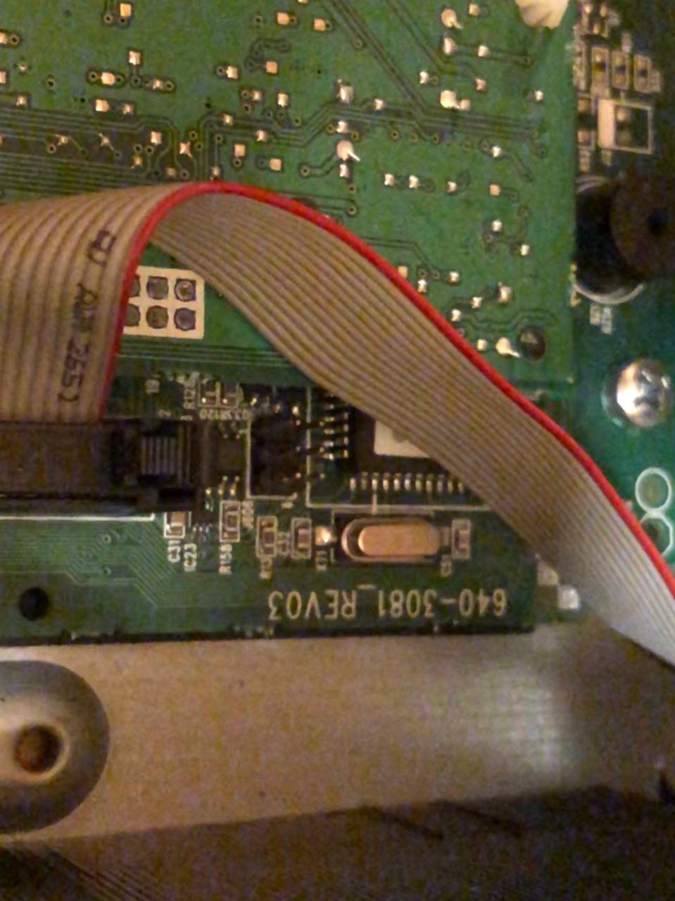
The signals from the controller are probably driven though a resistor, which allows you to hook up a USB to serial adapter. This blocks out the controller, and the UPS now listens to the USB serial interface (when connected). USB to TTL interfaces are about $1 on eBay, so I decided to attach an adapter permanently on the front of the unit.
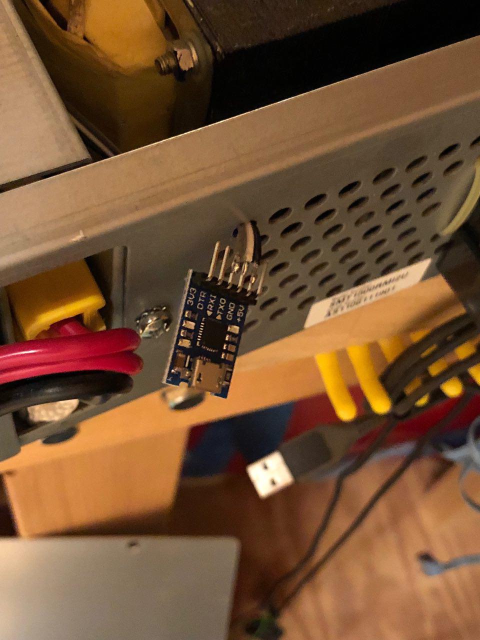
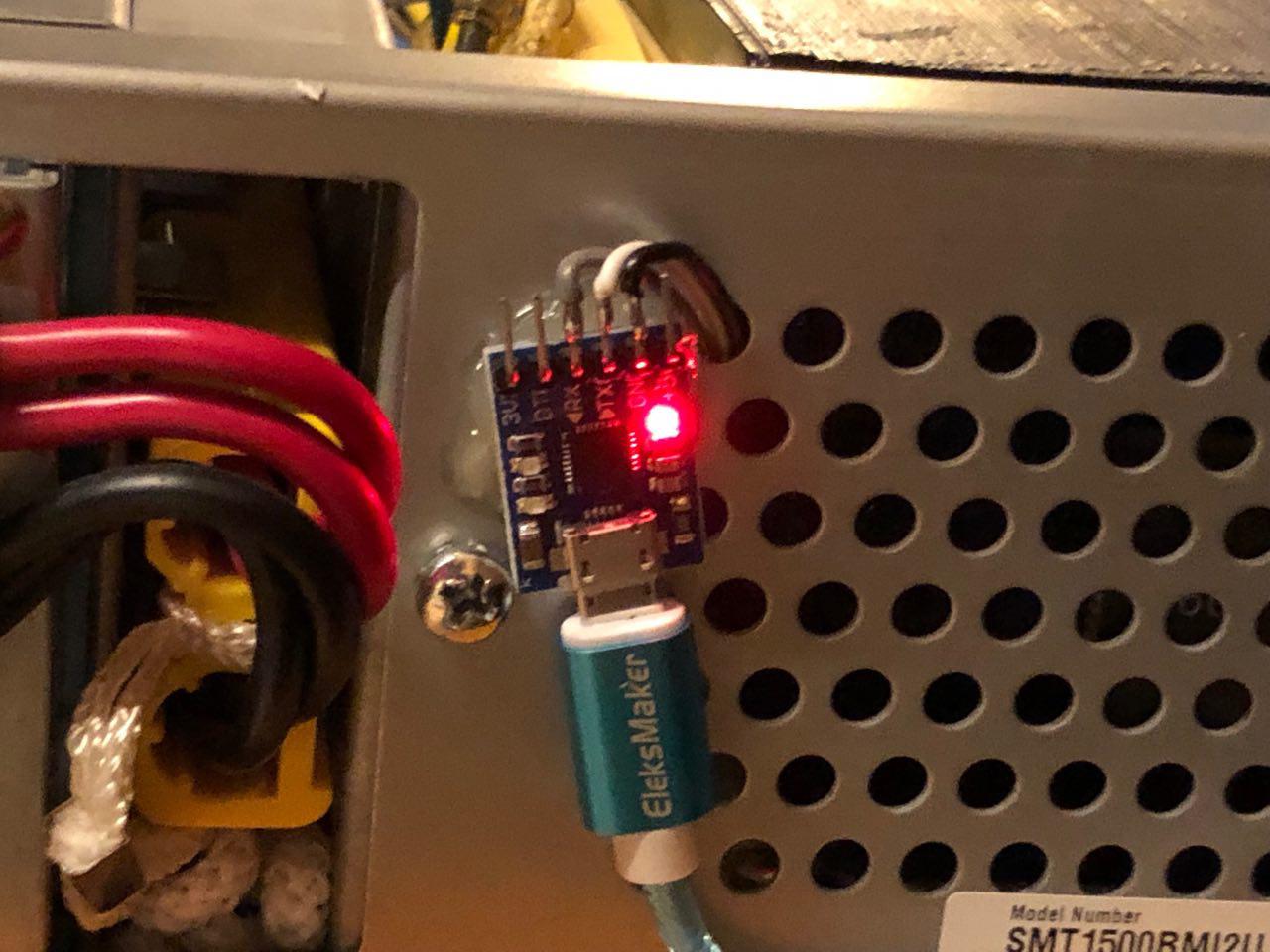
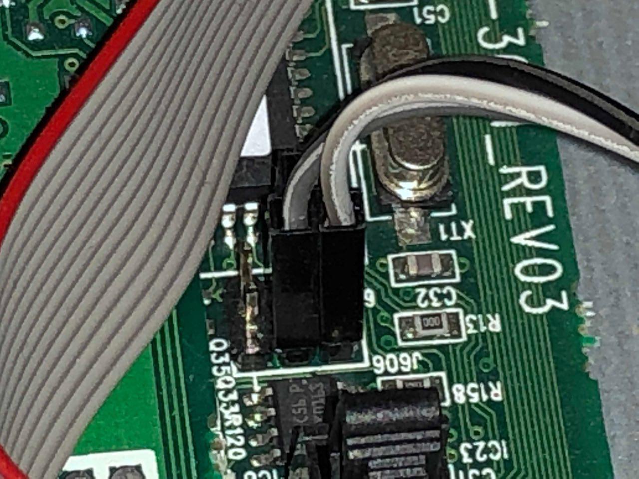
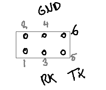
The pinout on this thing is up for debate, I'm pretty sure only pin 6 is marked, which would make the one on the left on the front pin number 1. The pinout as described on the post on overclockers works, but the pin numberings are confusing. My beautiful mspaint drawing is my take on the pinout. You can leave the pins connected to the USB adapter. As long as it is not powered, it shouldn't interfere with the regular communication. Boot the UPS before connecting the USB to serial to your PC. The UPS needs instructions from the controller board during powerup, or it won't work properly. In my situation, the communications ground on pin 4 was connected to the chassis ground. While vk2fro mentions you could get a ground loop, I don't see this happening anytime soon. At least not with power connected. I didn't use opto-isolators or a laptop, but used the desktop PC in my lab, and managed to not get my house burned down (yet). Your milage may vary, I assume no responsibility whatsoever.
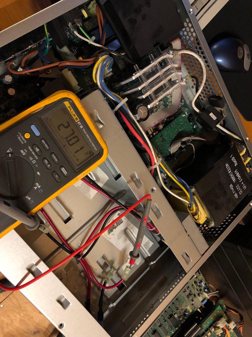
Adjusting the voltage is now fairly easy. I didn't hook up a capacitor, but just left the battery terminals floating. The UPS wasn't too happy about this, and kept warning me the battery wasn't properly connected. This doesn't matter though, the charger is still bringing the battery terminals up the floating voltage. Time to adjust the voltage!
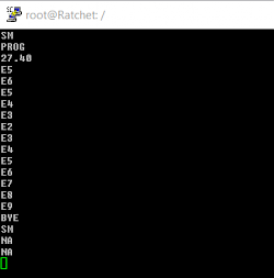
Start a terminal session at 2400 baud. I use PuTTY, but whatever.
- Press 'Y'. The UPS should answer 'SM'. If it doesn't, you probably didn't follow my carefully prepared instructions :)
- Press '1', and after a second or so, press '1' again. The UPS will enter programming mode, indicated by a 'PROG' response.
- Now press 'B'. The UPS will display the internal battery reading. It's probably way off. Enter '+' or '-' to adjust the float voltage. The UPS wil respond with a hexdecimal calibration value.
Check your voltmeter, and adjust until you're happy with your voltage. I dropped mine down to about 27 volts.
- Enter 'R' to return to normal mode. The UPS should now regulate its float-voltage to your calibrated value, also with batteries attached. Mine was reading about 30 mV higher after attaching and charging the batteries, but that was still fine.
Your communications log should look a little like this, after calibration:
Many thanks to vk2fro and overclockers.com.au for providing the guide
Comments
-
can i connect it with serial port??????????
-
So, just to clarify, you can't just use the custom pinout RJ45 serial port on the back of these units? You have to go in and modify them? Or is this guide just for units lacking that RJ45 serial interface?
Much obliged,
Matt -
Yeah. As far as I can tell, the serial port on the back is for management only, not for configuring stuff like voltages.
-
I managed to connect to the internal serial port but I have two issues: A lot of short numbers keep appearing in the screen (in the overclockers forum says that it is normal, but thenthe command log shown is clean) , so I can't read the response to my inputs, and the other problem is that the command 1 doesn't work, but I'm not completely sure, since the other problem makes it pretty hard to follow.
-
Finally found the solution, a japanese blog had the same issue as me ( https://blog.goo.ne.jp/rabbit5151/e/8df2ebd3e61951aa455fa2af44d9b9b9 ) the trick is the PIN 6 that should be connected to RTS:
USB to Serial--------J606
RxD -------------------- (3)
TxD -------------------- (5)
RTS -------------------- (6)
GND ------------------- (4)https://blogimg.goo.ne.jp/user_image/24/b0/6d831b7ad5b3b9968a9a2283fc21c334.jpg
-
Also configure the USB to serial to 3.3v TTL.
-
very helpful
Thanks -
network management cards needs to be removed before attempting serial connection, otherwise it won't respond - took me a day to figure it out :)
-
Does it hold after reboot or do I need to change it again after an reboot ?
i'm using 7s liion pack (home made) and it works but i want 28v on the battery, is this possible?? -
I am about to do the as you on a 900BG UPS. I hope I'm gonna be able to adjust this floating until 29 or maybe 29,4 and the BMS will shutdown the line perfectly
-
I am about to do the same the as you on a 900BG UPS. I hope I'm gonna be able to adjust this floating voltage @ 29 or maybe 29,4v. The BMS will shutdown the line perfectly.
-
OK, but who tell me, what is voltage must be on this APCRBC159 as standard parameter? in other words, these 4 batteries 12V/12F*h are connected sequentally, i.e. for 48VDC in total at terminals of RBC,
or in two strings by two units sequentally, i.e. 24VDC at external terminals of APCRBC159?
Moreover, whether somebody knows what's the difference in external terminal voltage between old RBC24 (4 cells of 12V/9A*h) and this APCRBC159? -
Hi,
Thank you very much for detailed guide to adjust the float voltage in an APC SMT1500RMI2U. My device is quite an old APC Samrt-UPS 700 equipped with a network management card and a serial port on the backside of the UPS. I managed to the enter the smart mode even with network management card. In fact, the network management card interferes with the serial port and presents its login procedure. Either you are fast enough to enter Y - 1 - 1 and reach PROG in SM, or you simply login to the network management card after the login is presented. Then you may leave the network management card with the command 'bye' and you have a chance - if you are quick enough - to use the commands to reach PROG in SM. I can execute B for displaying the battery voltage and I see the adjustments +/- confirmed ia serial port. However, the issue is that the measured voltage does not change at all. It remains at 27.52 V. I have connected a charged capacitor instead of a battery and a voltmeter to check the voltage with two digit precision. I also left smart mode with R, and I unplugged the mains to reduce the battery voltage. However, after having changed B from originally 27.47 to 26.93 by pressing multiple times the - button, I could also not read any differences on my voltmeter, neither before R, after R, and also not after a short discharge of the battery.
Could these effects be related to the fact that the network management card is still plugged in? Could these effects be related to using the external serial port?
Best regards,
Peter -
After this procedures i lost UPS section in web?
https://prnt.sc/oCYF5zTDD8FT
maybe some solutions? -
Kyrylo Ivanov 2 years ago ↑0↓0
Thanks for this useful info. I am trying to use lifepo4 elements, and it works fine but doesn't use full capacity, it only discharges to ~40% because this voltage is 0% for a standard battery. Does anybody know how to change 0% battery voltage to lower value suitable for lifepo4? Both programming and soldering options are welcomed.
-
Could this be used to keep replacement LiFePO4 properly charge?
Max charging for LiFePO4 batteries is 14.6v (14.4v recommended) which comes to 29.2v (28.8v recommended). I have read on other forums that keeping floating voltage on LiFePO4 batteries high all the time lowers their usable lifespan.
how true is this?
-
Hey, I have a smx1500rm2unc that I am trying to do this on. Have it open and dont see that header anywhere. It has the same "serial port isn't a real serial port" issue (even with the official cable). I see 2 possible headers.
One 6 pin one on the vertical PCB that seems to house the "brain" and one 8 pin on on the card where the front panel and network card connect to. Neither one have any pins connected to earth/ground it seems.
-
Hello,
I have SUA750RMI2U model and have battery failure from ups point of view. Batteries are 27.8 V but ups show 8.5V. I can only adjust to about 10V by "B" Option. Maybe someone know what can be a problem here
Regards -
It sounds good to run a 16S LiFePO₄ pack with my SMT3000RMI2U, but I still have an issue using 90% depth of discharge. The SMT3000 has a low-battery cutoff at 42 V. Is there any way to adjust the low-battery cutoff voltage?