Dataman S4 1640 EPROM Adapter
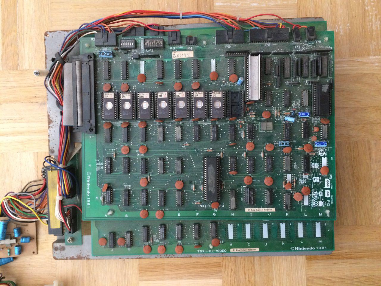
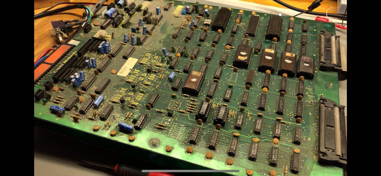
Sometime ago, I bought a cardboard box with some old arcade PCB's of of the internet for next to nothing. Much to my delight, it contained a bootleg Puck-man PCB, a Donkey Kong Jr. PCB, and a Nintendo's Popeye PCB. The Popeye PCB turned out to be a converted Skyskipper PCB. Slightly too valuable to keep around collecting dust, so I sold it on eBay to a collector. The Puck-man PCB worked nicely after some touchups, but the Donkey Kong Jr board gave me headaches. I traced most signals from the CPU, that seemed to be working nicely, but it only displayed some random garbage on the screen. What worried me a little was the fact that the EPROM's sitting on the main CPU board all had their little window exposed, and for all I know that board might've been sitting in bright light for a long time.
Time to buy an EPROM programmer/reader! I knew a Chinese programmer could be had relatively cheaply, but I wasn't looking forward to having to wait weeks for the thing to arrive. I also have pretty bad experiences with the software that comes with these kinds of products. It usually works barely, with poor compatibility on newer OS'ses or shady, blue-screeny drivers. Your milage may vary, and I'm sure there are all kinds of reliable programmers out there, but I wanted one now.
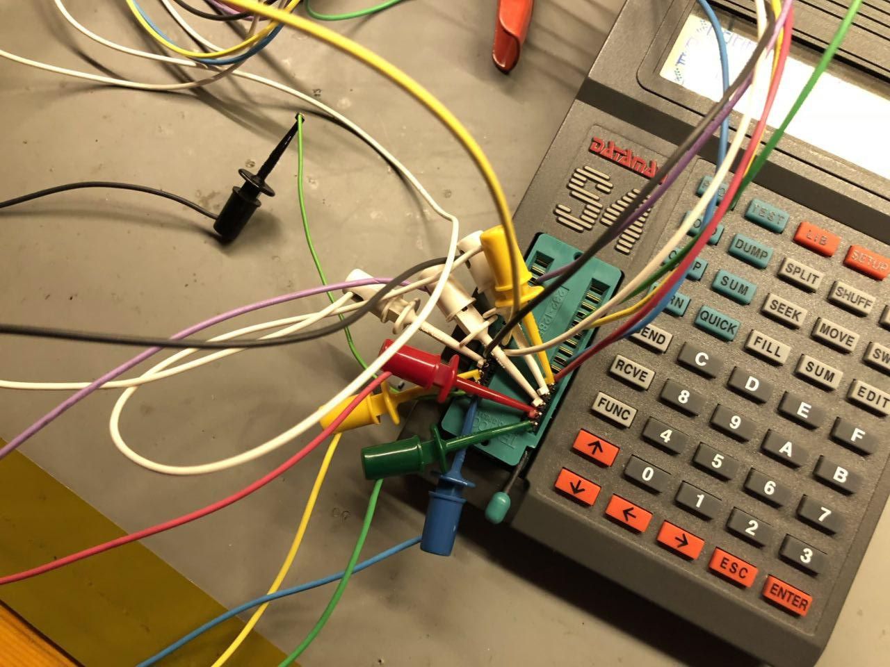
I found an older Dataman S4 programmer online, and picked it up on my way from work. On paper, the compatibility list was pretty long, as it seemed to have the capability to program nearly all EPROM types, including 16 bit variants. I didn't realise at the time that other devices would require the use of an adapter, but more about that later.
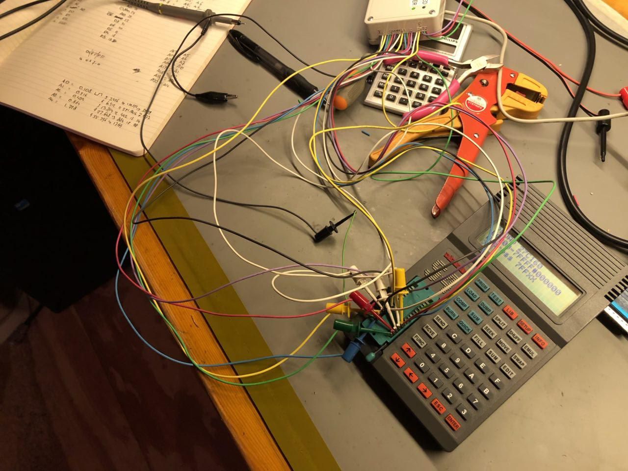
The Dataman S4 is a pretty neat, standalone, battery powered device that allows you to download or burn EPROM's without a PC. It's an older device, appearing first around 1992. It allows you to read, program, test, copy, and simulate EPROM devices, allowing you to make changes to your program on-the-fly. Pretty cool! The software to download ROM images from and to the PC is a little dated, but works perfectly. It came with a GAL adapter, a crapton of extra GAL's, the library EPROMs, emulation leads, booklets, adapter and also a nice little UV eraser. The UV eraser I bought on eBay turned out to be a death-trap, so I was very happy to have an alternative.
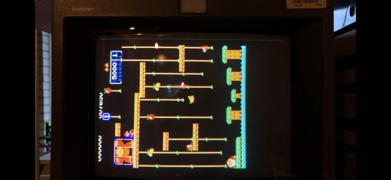
Turns out the only significant problem the DKJr was dead EPROMs; all the program EPROMs were partially erased, resulting in garbage opcodes being retrieved by the CPU. I burned the program EPROM's, and the board started working! Only problem I had was the fact that this was a Japanese board, and the sprites on the intro-logo screen were in a different order, producing a weird looking logo. After burning the graphics EPROMs to match the program, the board was now working perfectly.
I had some older 40-pin EPROMS that I found in various places a long time ago, all with their labels still on them. I was curious if I could use the S4 to get to their content, see if I could find some clues to ascertain their origin. It wasn't until then that I noticed the 32 pin ZIF socket on the S4.
Dataman sells an adapter to work with 42 pin EPROMs. This adapter sit on top of the 32 pins ZIF socket, and does some translation to allow 42 pin EPROMs to be read and written by the S4. 40 pin adapters were also available at one point, but Neil from Dataman informed me they sold out years ago. He also gave me some information about the way the battery is charged. Far more support than anyone could hope to expect on a product that was probably discontinued decades ago. For some pinouts, appropriate adapter schematics are provided by Dataman, and can ben found here. The '1640-adapter', however, is not listed.
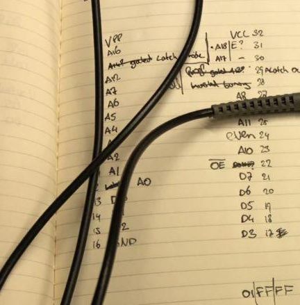
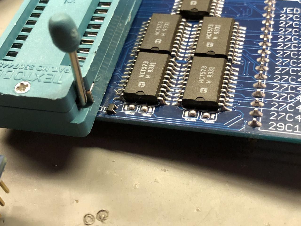
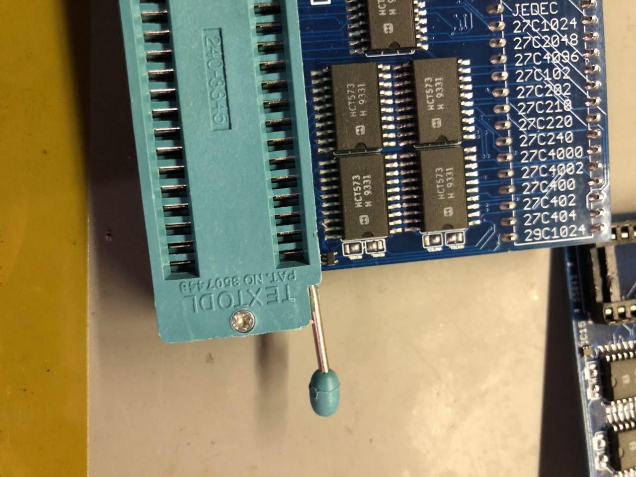
The library for 16 bit EPROMs can also be downloaded from their 'S4 Resources'-page. Starting a download of EPROM data without an adapter present in the socket also works fine, and this invited me to do some probing of the different signals on the 32-pin ZIF socket. Using a logic analyzer, datasheets of 16 bit EPROMs and careful measuring, I managed to reverse-engineer a schematic that, at least in theory, could work. I made an assumption that proved to be correct; in order to access the additional databits and address lines, you would require some kind of shift register or latch. It looks like the adapter uses 1 latch to access additional address lines, and would require some kind of bus interface to map the 16 bits databus onto the regular 8 bit bus.
In 16 bit mode, the programmer sacrifices some address lines in order to provide latching and output-enable signals to the adapter. There were two signals that would appear during reading, in close proximity to eachother, taking turns in a temporary high-to-low-to-high transition. By patching this line into the databus, it became quickly apparant that the programmer uses these lines to split the 16 bits bus into 2x 8 bits, and requests each part on it's databus sequentially. Only on odd addresses, the toggled line would show as a 0 on the databus when trying to read en eprom. On the even addresses, the connected dataline would read as a 1. That was enough evidence for me, these were the databus-select lines.
In burn-mode, the programmer would need to somehow supply 16 bits of data through an 8-bit bus, as a 16 bit EPROM is burned word-by-word. This would also require latches in order to set up half of the bus, then setting the other half.
I figured out how the address bus was mapped by entering address-line boundaries in programming mode, and see what line toggled. The programmer/adapter should ignore A0 internally, as this line would normally be toggled every byte. As 2 bytes are being read simultaneously, the A0 is not actually connected to the EPROM, but A1 is connected to the EPROM A0 line. A13(A12) through A20(A19) are mapped onto the regular address bus, and an extra latch strobe is fed into the 5th and final latch to make these lines available.
The only thing I couldn't figure out, was the order in which the data would be read. Depending on the endianness, the odd bytes would be either the upper or lower bus 8 bits of the 16 bits bus, and the even should be the other.
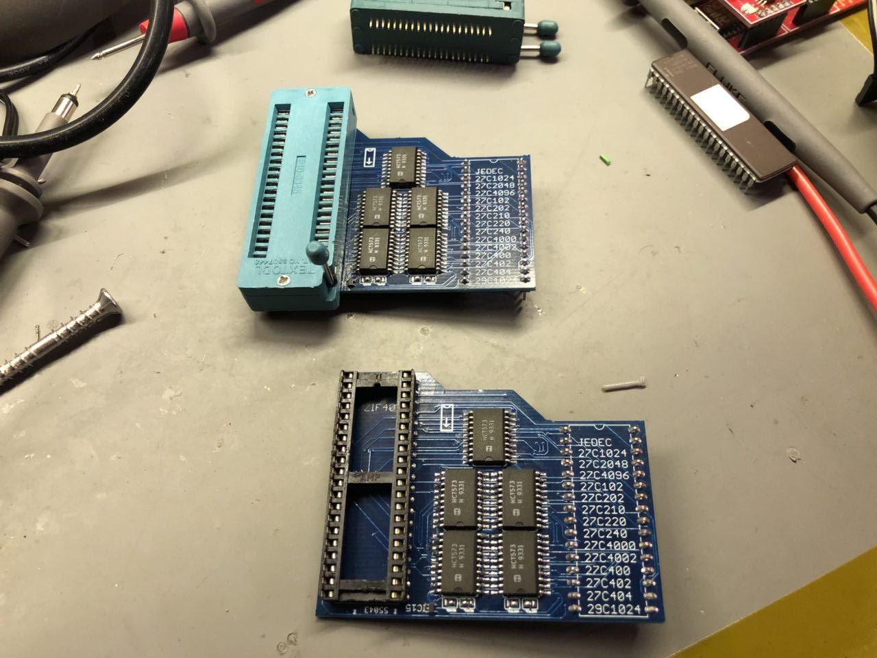
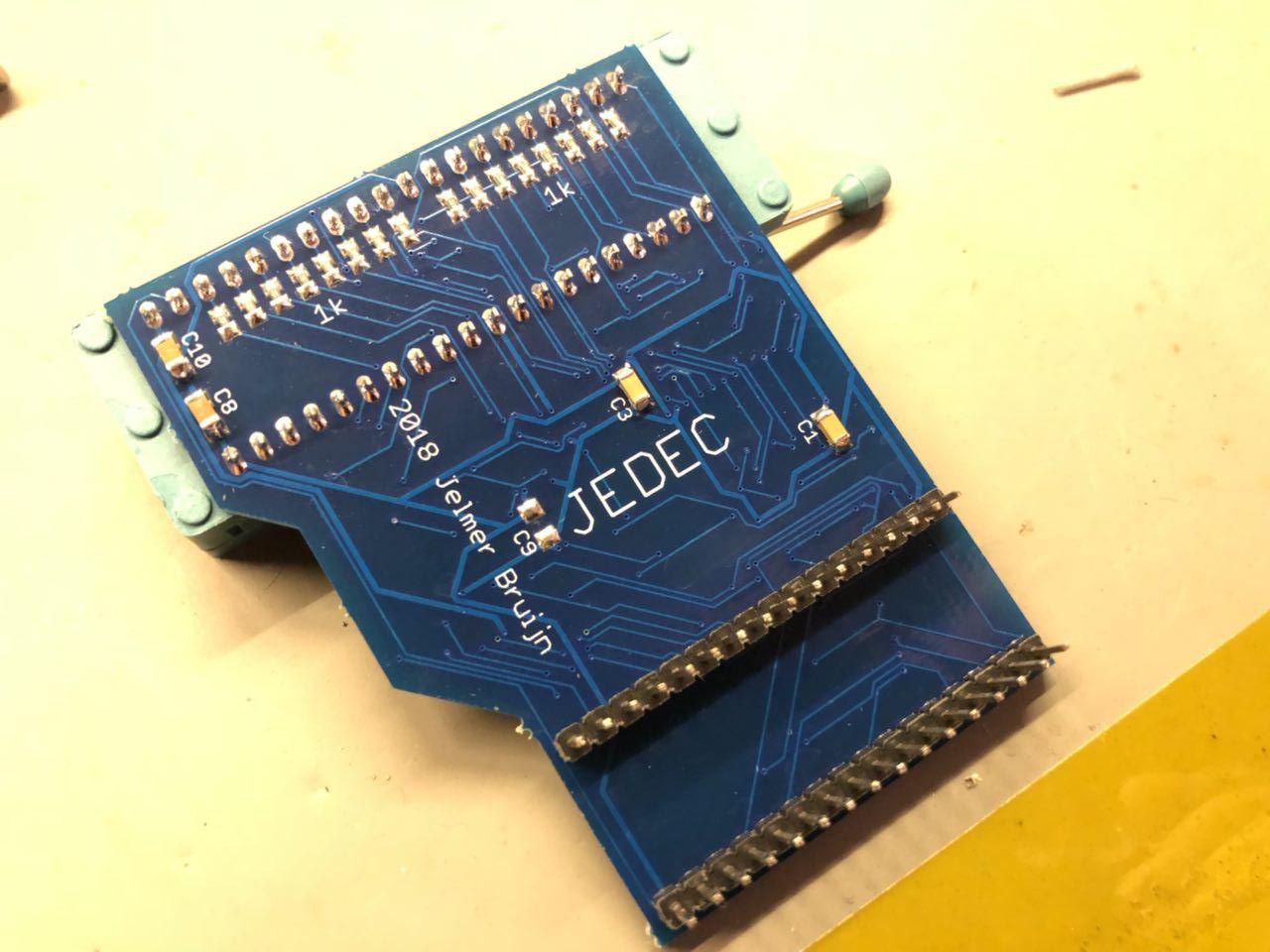
After a lot of pondering and looking at the analyzer dumps, I drew up a schematic in Eagle with something that I thought made sense. I chose to include little solder bridges on the adapter, that allow you to select the endianness for reading and writing. After a few weeks, the boards arrived, and I quickly tried if it worked. No such luck, unfortunately. The S4 kept giving me a 'VCC SETTING ERROR' message. My scope revealed the VCC was tapering off up to about 3v, instead of ramping up steadily like it's supposed to. After adding small resistors to the upper/lower select lines, the problem was resolved, and my homebrew adapter was happily reading and burning EPROMS! It's probably pretty straightforward to make a 42-pin adapter as well, but as Dataman is still selling those adapters, I'm not making schematics available.
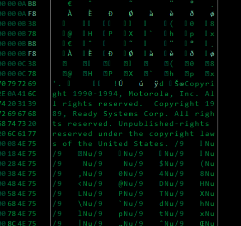
So, what was on those old 27C210 EPROMs? Nothing special... Looks like they came out of Motorola telecommunications equipment. I couldn't find many strings, but this one stood out:
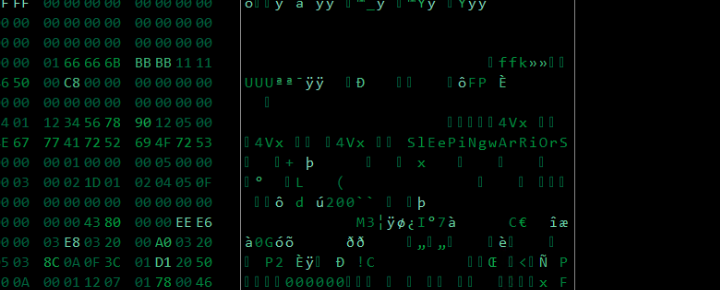
SlEePiNgwArRiOrS, if you're still out there, I salute you!
I can't find an awful lot about 'Ready Systems Corp.', but they seemed to produce some kind of RTOS system. Probably what this thing was running back then. The stuff below the copyright notice is probably some kind of jump/interrupt vector table.
My thanks to Dataman! I know very few companies that still support their legacy products like they do, and still maintain a website with all the relevant information for a device that was built well before internet was widely available.
Schematics are available here
I do have some boards left over, as 1 adapter board is all I really need. If you need a PCB, drop me a line ( mail AT <this domain> ) and I can send you one at shipping cost.
Comments
-
Hi could you send me one please? Ive got an S4 with no adapters just unit only. I had someone look ar your schematics on GitHub and do gerbers but they said parts appeared then disappeared ?
Regards Richard
-
Do you have any PCB's left as I would like to buy one.
I have tried sending you an email
(mail AT jelmerbruijn.nl) but not got any reply.
Kindest regards,
Martin Blay. -
Benny Boogaert 7 years ago ↑0↓0
Hallo Martin, Leuk stukje, Ik kwam het toevallig tegen bij mijn zoektocht naar een GAL adapter voor mijn eigen S4, Weet jij toevallig of die nog ergens te koop zijn? of zou ik er misschien zelf een kunnen maken? ik ben handig met electronica. Ik hoor graag jouw reactie.
M.v.g. Benny -
Hi,
very interesting article. So you also have the GAL adapter? I would be very interested what's in it - i have a S4, but i'm missing the GAL adapter and would like to build one.
Thanks!
-
Hi,
I'd like info on the GAL adaptor too if possible, photos of what is inside it would be useful, perhaps I could make a DIY version? I have an S4 and didn't realise that it needed an adaptor for GAL or CPLD chips.
cheers. -
Also interested in what's inside that GAL adapter.
I realise Dataman still sell those, too .. but it's £300 and GALs are pretty much obsolete.
I've started looking at the programming signals in GAL mode and they almost make sense for just pin-scrambling, but there must be more to it.