Blocks and vectors
After this, data is transmitted in 11 blocks of 8x 32-bit words. Data is sent in interleaved blocks of 8 words. This means that the first transmitted bit in the block will be the first bit of the first word, the second bit will be the first bit of the second word, and so on. The 9th transmitted bit is the second bit of the first word.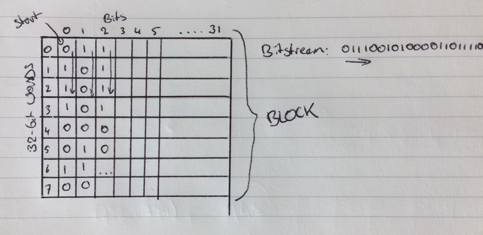
This scheme effectively reduces the effect of fading and small interruptions in reception, as the effect is spread out over multiple words. Pretty clever! The BCH code help to recover 2 bit errors per word. It took me quite a while to figure out that bits were transmitted in this order; not sure why I overlooked this in the patent as it is explained clearly.
BIW
The first word of the first block is always a Block Information Word. This word contains information about the location of addresses and address-vectors. The structure is as followed:
+----+----+----+----+----+----+----+----+----+----+----+----+----+----+----+----+----+----+----+----+----+------------+--------+
| x0 | x1 | x2 | x3 | p0 | p1 | p2 | p3 | a0 | a1 | v0 | v1 | v2 | v3 | v4 | v5 | c0 | c1 | m0 | m1 | m2 | 10 bit CRC | parity |
+----+----+----+----+----+----+----+----+----+----+----+----+----+----+----+----+----+----+----+----+----+------------+--------+
- p 4-bit priority addresses at the start
- a 2-bit End of Block Info
- Indicates the start of the first address (a1-a0)+1 (1-4) and the presence of up to 3 extended BIW words
- v 6-bit Start of area
- c 2-bit carry-on (indicating information for addresses pager will follow in the next X frames)
- m 3-bit System frame collapse (2^n collapse)
- 0: all frames received
- 7: 1 out of 128 will be received
- x 4 bit checksum
If the 'end of block info'-value is larger than 1, one or more extended BIW words are present in the block. These extended BIW words are used for extended system information and FLEX time information.
Then, a list of addresses is sent. The addresses can be of two different types: Short or long. I've only implemented the short variant, as long addresses are not in use on the P2000 system. If you want more information about long addresses, I suggest the patent; every bit of information should be there.
(almost)Every address has a corresponding vector. The vectors appear right after the last address. The first vector is aligned with the first address. Exceptions are vectors for long addresses, as these addresses occupy two address words. The vector-word location associated with the first word of the long address contains the actual vector, the second word is used to store the message header, and the remaining words of the message start at the location indicated by the vector.
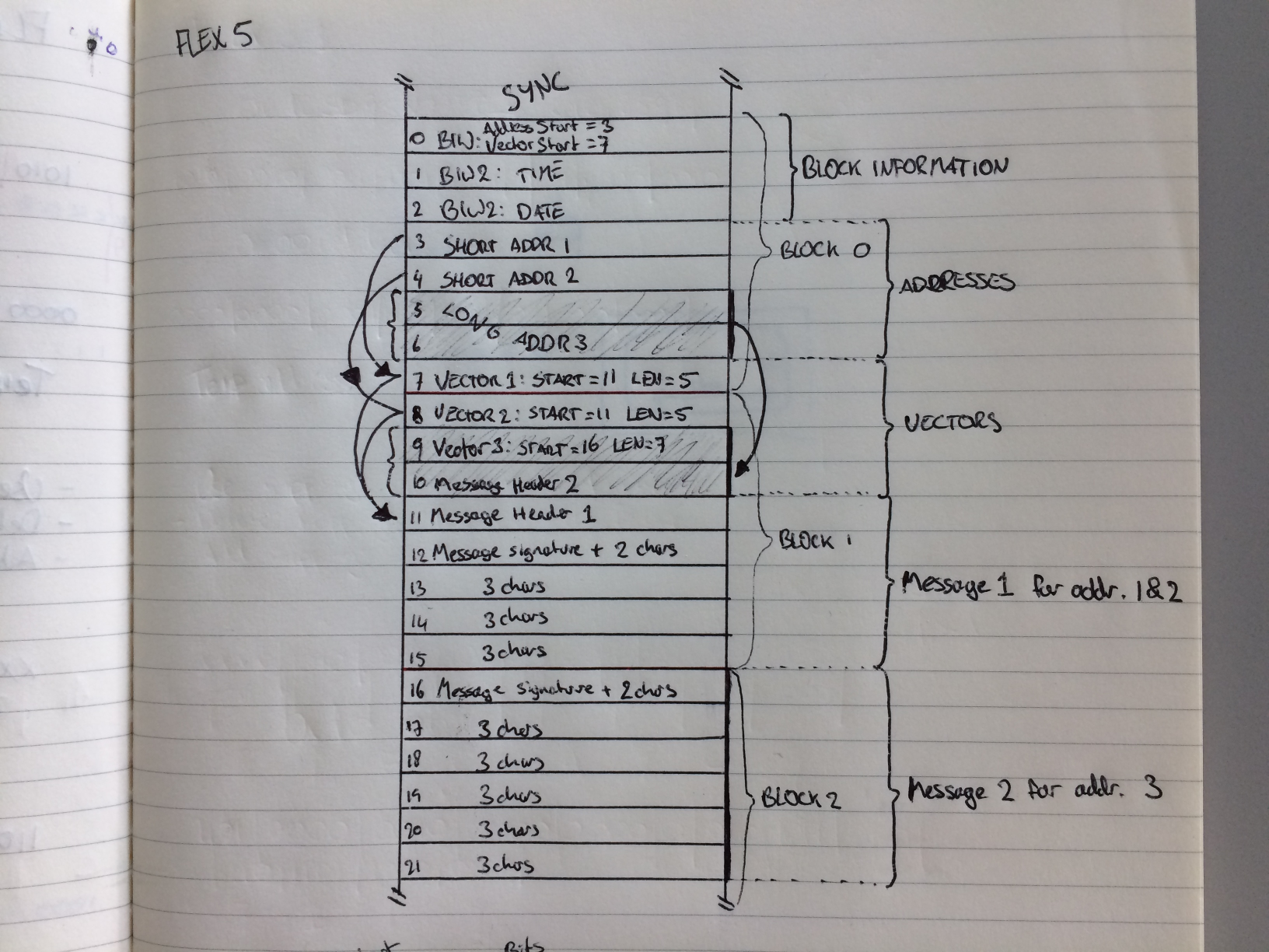
There are 8 different vector types for different types of alerts (such as tone-only or numeric). The potentially interesting ones are:
- 1: Short instruction
- 5: Alphanumeric
- 6: HEX/Binary message
- 0: Secure message
The structure for these messages are all the same, with v0 to v2 indicating the message type for the decoder.
+----+----+----+----+----+----+----+----+----+----+----+----+----+----+----+----+----+----+----+----+----+------------+--------+
| x0 | x1 | x2 | x3 | v0 | v1 | v2 | b0 | b1 | b2 | b3 | b4 | b5 | b6 | n0 | n1 | n2 | n3 | n4 | n5 | n6 | 10 bit CRC | parity |
+----+----+----+----+----+----+----+----+----+----+----+----+----+----+----+----+----+----+----+----+----+------------+--------+
- x 4-bit checksum
- b 7-bit message start
- n 7-bit message length
- v 3 bits vector type
- 0: Secure
- 1: Short instruction
- 2: Short message
- 3: Numeric vector
- 4: Numeric vector with format
- 5: Alphanumeric
- 6: Hex/Binary
Another commonly used type for emergency services is the Short Instruction vector. This vector could be used for other stuff, but in the information I found in the patent, only the 'Temporary Address Activation' seems specified. This vector instructs the pager to listen to an additional 'temporary' address for a certain frame. This allows the system to send one message to a whole group of recipients simultaneously, be specifying 'group' addresses before sending the message. 16 temporary addresses are reserved for this purpose.
+----+----+----+----+----+----+----+----+----+----+----+----+----+----+----+----+----+----+----+----+----+------------+--------+
| x0 | x1 | x2 | x3 | 1  | 0  |  0 | i0 | i1 | i2 | f0 | f1 | f2 | f3 | f4 | f5 | f6 | a0 | a1 | a2 | a3 | 10 bit CRC | parity |
+----+----+----+----+----+----+----+----+----+----+----+----+----+----+----+----+----+----+----+----+----+------------+--------+
- x 4-bit checksum
- 100 - 'Short instruction Vector'
- i 3 bits, instruction type (000 for Temp. Address Activation)
- a 4 bits, temporary address to listen to (16 addresses starting at 0x1F7800)
- f 7 bits, frame where the pager will listen to the temporary address
This ability might be the reason FLEX was chosen over other standards for use with P2000, as it reduces the amount of transmissions needed for big pager groups