Hardware
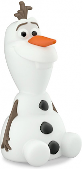
We bought a Philips Olaf night-light a while a go for my daughter. It was a nice little toy, that lit up for 5 minutes after turning it upside down. After a while, it stopped working. I suspect a little battery leakage killed the little PCB. After cleaning the battery goo, we let her keep it as a simple toy.
After a while, I figured out another use for Olaf. I thought it would be nice to reuse Olaf as an alarm clock, lighting up in different colors to indicate wheter or not she's supposed to get up, or maybe convince her she's supposed to stay in bed a little bit longer.
I figured the easiest way to do this would be an ESP8266 with some RGB leds. I had a few spare ESP-01's left, and some leftover pieces of WS2812 led strip. Combined with a 3.3v linear regulator, this was basically all I needed. I worked out a schedule that could work, in theory. These are the parts needed for the conversion:
- one Olaf, dead or alive
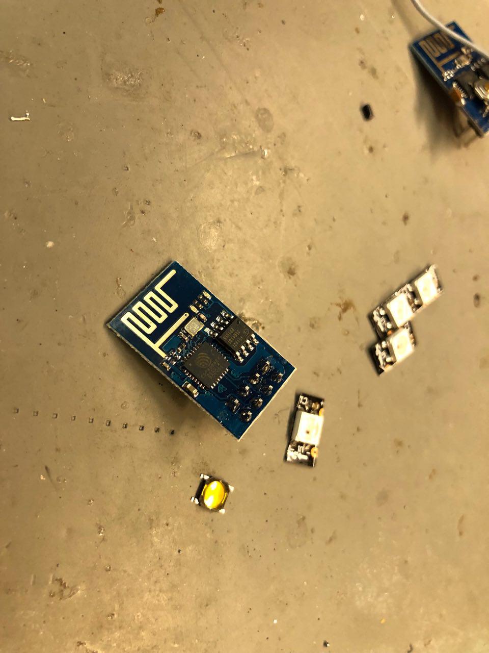
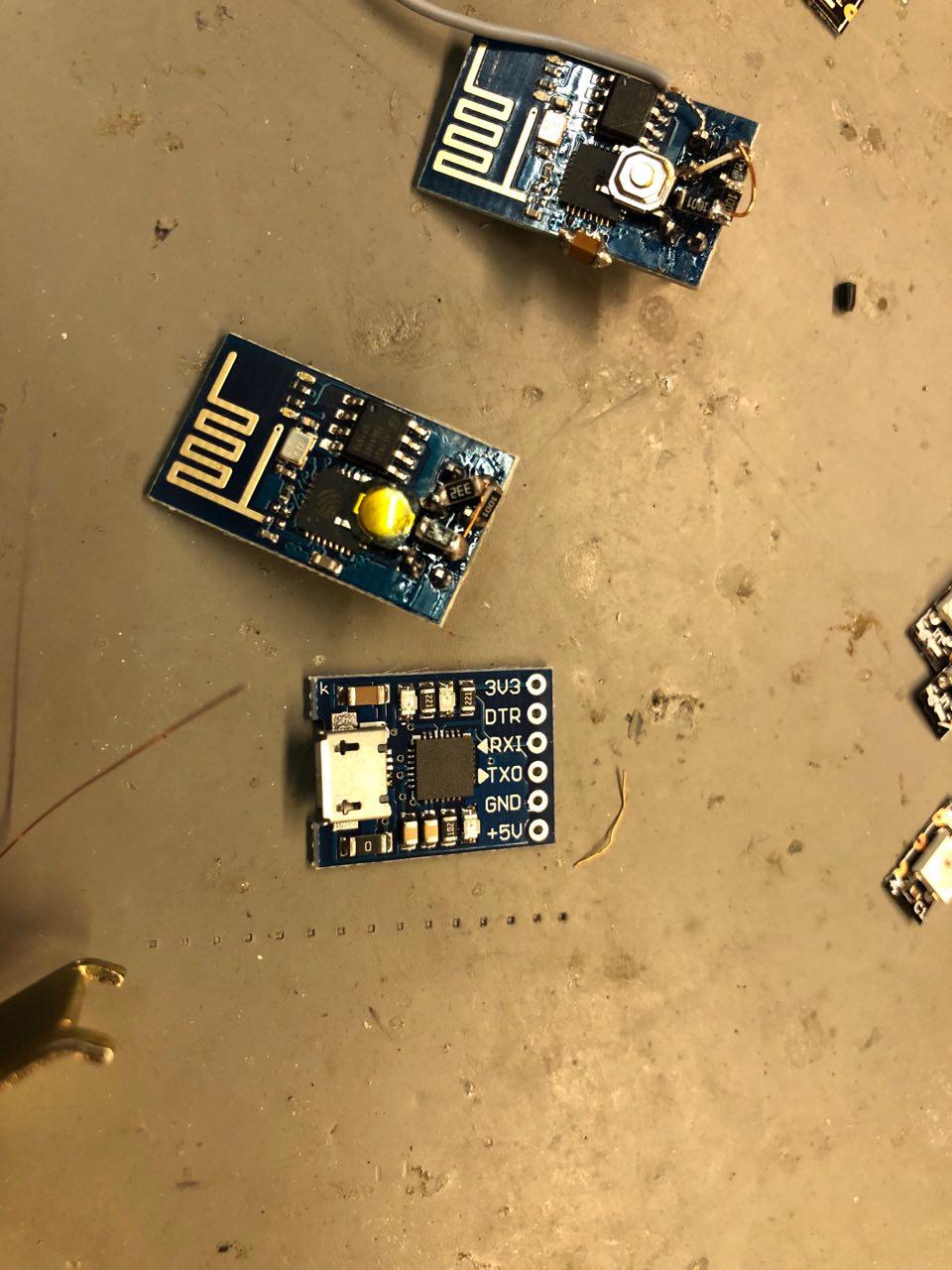
- ESP8266 (ESP-01)
- A few WS2812 leds
- 3.3v regulator
- Capacitor
- Diode
- USB to Serial TTL converter
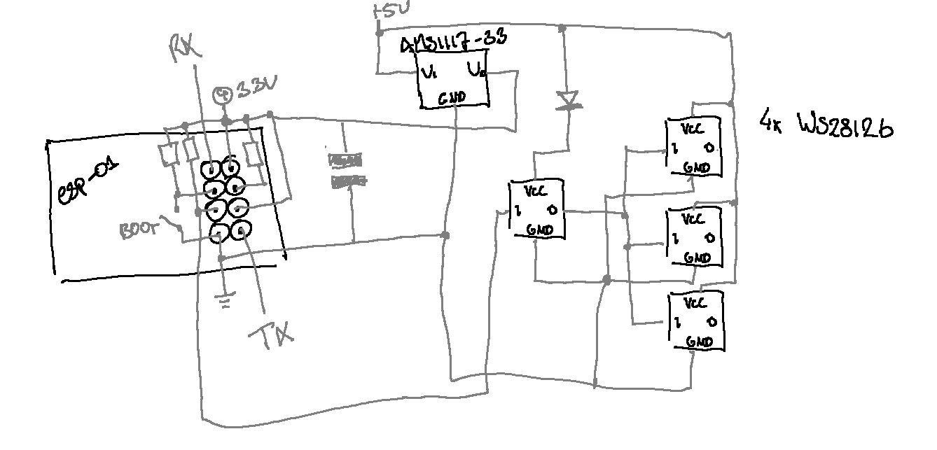
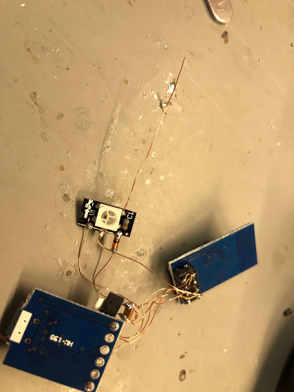
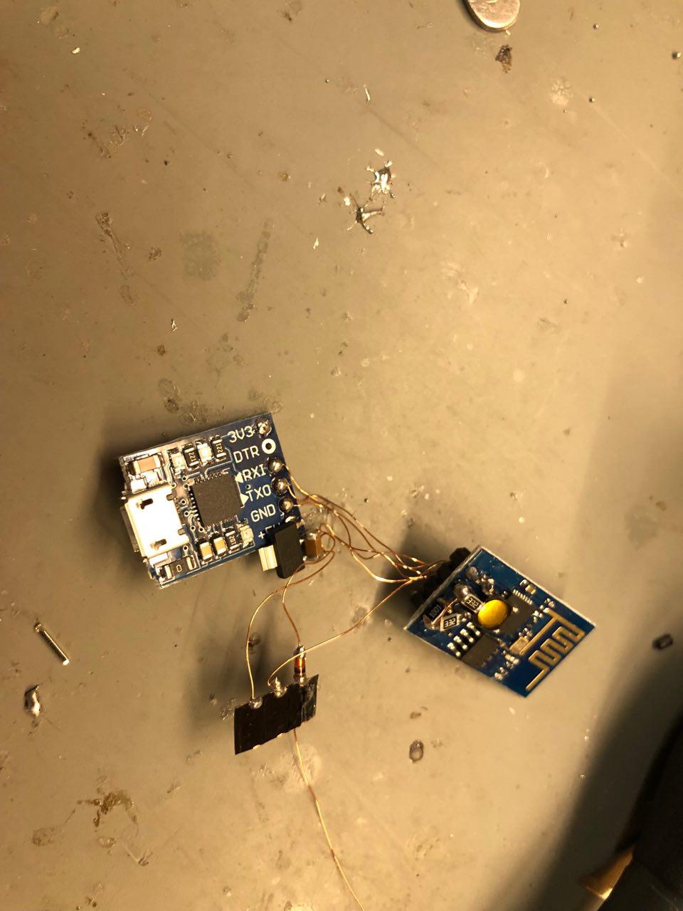
The schematic is pretty straightforward. It uses a minimum amount of pull-ups at the ESP-01, and contains a little bit of a hack to ensure the WS2812 leds are driven reliably. The 'hack' can be found here. It uses a diode to drop the VCC for the first WS2812, bringing the 1 on the 2812 up to 0.77*VCC. This is enough to drive the first led, the 3 other leds are powered straight from 5v, bringing the high-value of the data port to 0.86*VCC. Works like a charm. I could've daisy-chained the 3 leds in series, allowing for individual led control, but that would be of very little use in the white-diffuser-translucent Olaf doll.
I wired everything together with magnet wire (enameled copper wire), which allowed me to fit all the separate parts within the existing plastic support structure. The resistors and button were soldered directly on Olaf's ESP8266. By passing the 5v from the USB-to-serial adapter to the rest of the schematic, the USB port serves both as a programming adapter and power port.
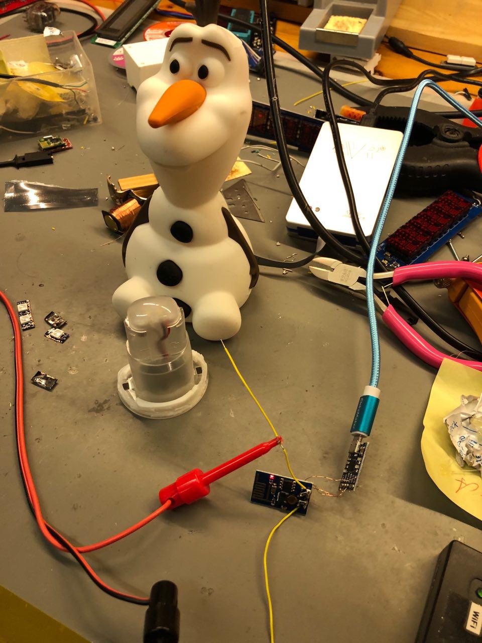
I had to cut a small hole in Olafs rear to allow access to the micro-USB plug. The rubbery plastic is thin enough to let most micro-usb cables work without a hitch. The LEDs were attached to the small plastic dome on the inner structure that can be seen in the leftmost picture. Copious amounts of hot-glue holds everything in place.
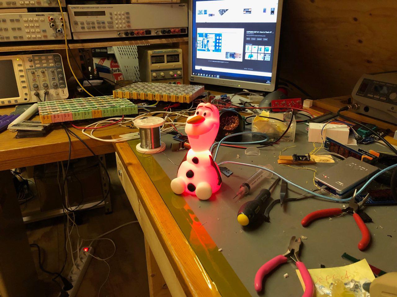
All I had to do now, is apply some power...
IT IS ALIVE!